As a Christmas gift for my partner, I wanted to get a press for paper making, lino printing, and general arts and crafts. I could not find any cast iron presses on eBay that were both cheap and near my city, so I decided to make one, as I had some leftover timber from building my workbench. The final press is suitable for A5 paper and can fit a 100 mm tall stack.
Every year I fall into the trap of thinking that a handmade gift will be quick and easy and every year I am wrong. But, despite the very late nights I have really enjoyed the process of making this and I’m proud of the final result.

In paper making, newly formed, wet paper sheets are transferred from the mould screen onto an absorbent surface like felt. This process is called couching. One of the ways to remove water from the paper is to press the paper/felt stack. Helen Hiebert shows pressing equipment ranging from a simple sponge to a hydraulic press. https://youtu.be/MjdpBYzZ1qk?si=sF0jYBSY5EmuSIja&t=291

I also took heavy inspiration from the Uri Tuchman Pigeon printing press
https://www.youtube.com/watch?v=69W5ZFmAPIU
https://www.youtube.com/watch?v=h8EzpBvPtE4

I first started the design in CAD to get the proportions right. It features two plattens (the wide boards that squeeze either side of the paper), two side pieces and a top piece.


I started by cutting the timber to length and jointing one edge with a hand plane. This timber was not used for my workbench because of how twisted and warped it was. This made it hard to reference a flat side for edge-jointing to exactly 90 degrees, so I just eyeballed it.


After edge jointing I glued up the timber for the plattens. Three lengths were held together using ratchet straps and F-clamps to help with alignment. This was surprisingly uneventful for a glue-up!


Next was ripping the panel down to the correct width. I’ve never figured out how to get the best out of the ripping side of my pull saw, and long rip cuts like this usually wander off course. Instead, I like to make several cross cuts and then pry off the waste in big chunks with a chisel, followed by planing. I left the width a few millimeteres oversized, as the top and bottom flat reference faces still needed to be established.


Next the top and bottom faces of the plattens were made flat and parallel using a hand plane. I used the “winding stick” method to remove the twist from the platten, and planed at -45, 0, and +45 degrees to the grain direction. For a board this small relative to the length of the plane, this was very straightforward.

In one of the boards, I got unlucky with the location of a resin pocket. I planed off this corner, cut a corner from a spare board, and glued it on to cover the resin.


Once I had one side of the platten flat, I used calipers to mark the thickness of the platten, and planed down to this line to flatten the other side.


Now that the large flat reference surfaces had been established, I planed the boards to their final width and length, making the edge faces 90 degrees at the same time, checking this with a square.


The usual late night wood shavings chaos:

I repeated this process with the remaining timber pieces for the top and sides of the press. Dimensioning timber using only hand planes takes a lot longer than just chucking it through a thicknesser or jointer, but it’s super satisfying, way less noisy/dusty, and great for developing hand-plane muscle memory skills.

The leadscrew I chose is a standard M20 threaded rod with a 2.5mm pitch. To retain the leadscrew, I found a comically large M20 threaded insert. It has a coarse external thread that screws into the top piece and a M20 internal thread for the leadscrew. Out of interest, I first tested the strength of the insert on a scrap piece by using an M20 rod to lever the insert out destructively. The surrounding timber split before the threads pulled out so I am confident this is strong enough for this application! After drilling a 27mm hole with a forstner bit I used an M20 rod and a jam nut to install it into the top piece.


Next I cut the mortise joints in the side pieces to retain the top piece.


Next I cut the matching tenons in the top piece and started to fit it into the mortise. To find the high spots I rubbed a ruler on the joint which left some marks to show where to shave down with a chisel.


The bearing plate sits on the top platten and is attached to the end of the leadscrew to allow the platten to be lifted. It has a 20 mm hole for the leadscrew with a 26 mm counterbore for the acetal washer.

Next came the chamfering. I wanted the chamfers to stop before the joints to imitate the deck beams on the ceiling of a wooden boat. Normally I just eyeball chamfers, but I wanted them to be consistent so I marked them all out. I used a chisel to carve out the stopped-chamfers and a block plane for the full-length chamfers.


After a 220 grit sanding and a dry fit, it was time for the glue-up. The side pieces are held to the bottom platten with a large-area glue joint and 2 screws for clamping and alignment. These screw holes are counterbored and capped with a 10mm hardwood dowel to hide the head of the screw. The mortise and tenon joints also had dowel holes drilled to strengthen those further.

The glue-up was stressful! Doing it at 12.30am did not help, but I was on a tight timeline. The mortise and tenon joints fit very tightly, and I forgot that this always makes it difficult to assemble when glue is added. All the joints were tight enough with good squeeze out and no major misalignment. Trying to do this quietly to avoid disturbing neighbours was an unhelpful constraint – this taught me that fast glue-ups should be noisy and they are not a nighttime job (I used a manual screwdriver instead of the drill and installed the dowels with the long clamp instead of a mallet).

Flush trimming and planing dowels is always very satisfying.


I gave the wood parts 2 coats of water based varnish. It looks “good from far but far from good”!

The rest of the pieces. The countersunk acetal washer was made on the lathe – it’s used to hold the top platten to the lead screw via the bearing plate. The M20 leadscrew rod was modified on the lathe to drill and tap the hole for the acetal washer. At the handle end, the M20 threads were turned down and then a 8.5 mm hole was cross drilled and countersunk on a mill. The handle is a 8 mm cold-rolled mild steel rod with threads cut on each end for the red balls (bought off-the-shelf).


Assembly time! Through initial testing I found that there was some friction between the acetal washer and the top platten / bearing plate. This friction increases when the press is in its fully-clamped position. The friction was enough to loosen the M6 countersunk screw holding the acetal washer to the M20 leadscrew. This meant the top platten fell off the leadscrew, preventing it from lifting up when the leadscrew is retracted.


To counteract this, I applied medium strength blue threadlocker (I wanted high-strength/red, but on Christmas Eve blue was all I could find at short notice) and torqued the countersunk M6 screw as hard as I possibly could. This is a bit of a design flaw, and if I was doing this again I would turn a groove into the leadscrew on the lathe, and use a circlip to retain the bearing plate instead.
The flathead screws came from an assorted bin sourced from my partner’s dad’s shed.
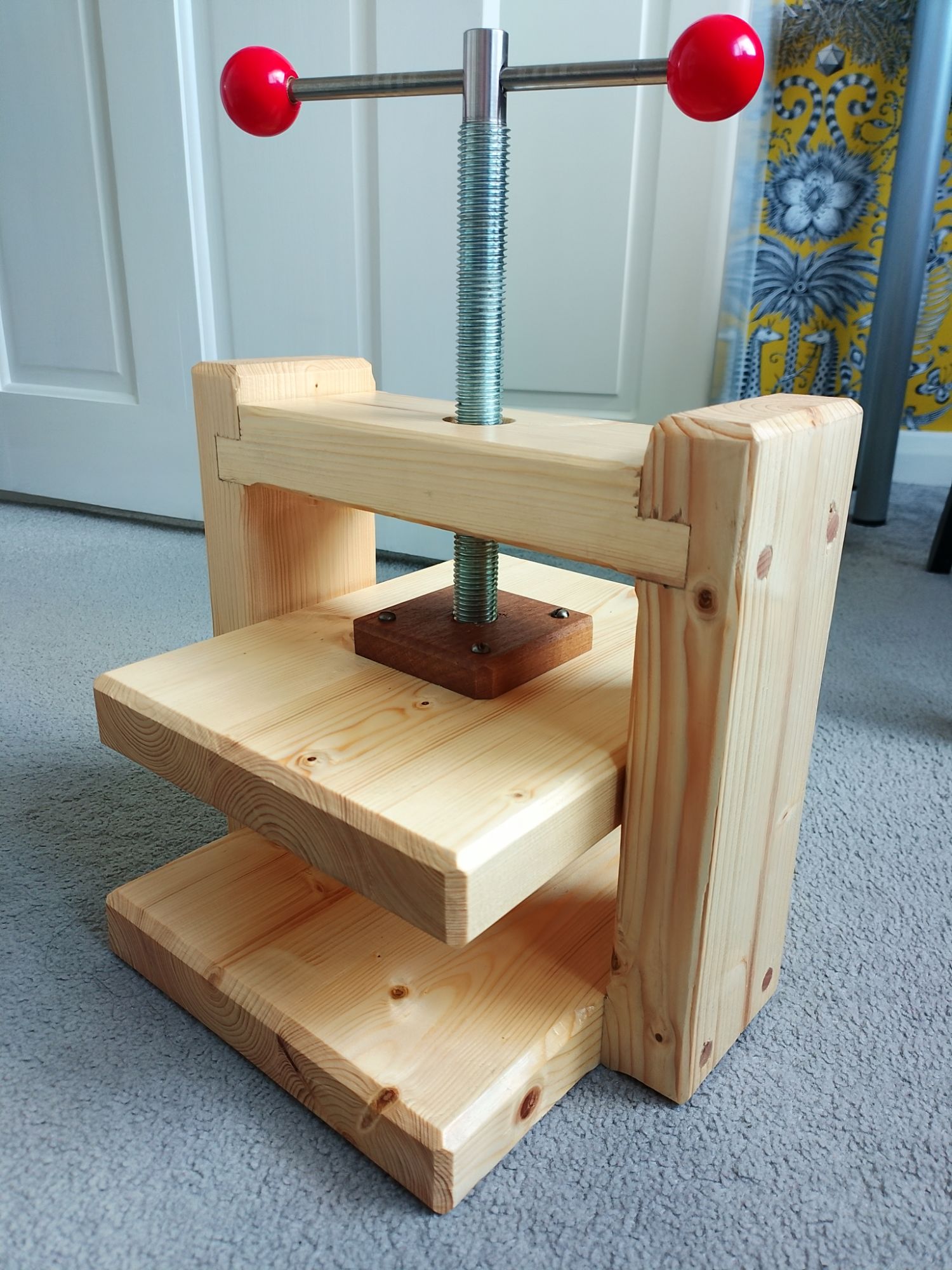
And, it’s done!
What I’m especially happy with:
- The red handle balls look brilliant.
- The press squeezes hard.
- The chamfers took way longer than expected, but I’m really pleased with the overall flow of the lines and how it ties in with the joints.
- I got a lot of hand planing practice and developed some great muscle memory.
Even better next time:
- A press has one function: for the top platten to advance down to clamp the work and then retract up again to release the work. Due to the friction issue, in the future the platten may fall off the leadscrew and no longer retract.
- I could have invested more time on planning the mechanism and less on chamfering! Essential functional requirements should come before aesthetics.
- If making a clamping device in future, I would separate the clamping elements from the retaining elements.
- Don’t try to do glue-ups at night. They are stressful enough anyway without the added constraint of being quiet.
The press will be used soon, either for paper-making or lino printing, or something else. Some pictures of the results will be added later.
Leave a Reply