Summary pictures


Intro
It’s time to continue to work on the nickel/copper patterned billet that I started in this post: First attempt at mosaic patterned nickel/copper
Previously I made a billet with alternating nickel/copper layers, with “S” and “C” cross sectional patterns. These are fundamental building blocks for mosaic pattered billets.
The aim of today’s experiment is to create a more complex cross sectional pattern by cutting then re-stacking the billet and rolling it out.
Since the last post I also:
- Bought a used rolling mill from eBay. The roller height adjustment gear was missing so I 3D printed one with a hand wheel.
- Started to read Steve Midgett’s fantastic Mokume Gane book: https://www.mokume.com/mokume-gane-a-comprehensive-study/table-of-contents.

Method
First I rolled out the billet to 64 x 6 x 2 mm, all under one anneal. The edges started to crack a lot, although I think there were old cold-shuts opening up, as well as new cracks forming from the rolling. The cross section showed the “S” pattern had compressed.
The rolling process bent the billet a lot. I annealed the billet to soften it and then manually straightened it with pliers.


Next the billet was cut into three equal length pieces, and flattened as much as possible by squeezing hard between the parallel pliers. In the dead soft state this works surprisingly well.


The surfaces were sanded with 400 grit to remove oxides. This was done poorly because I was rushing, and at the time I was relying on the flux to remove the oxides for me (more later on why that doesn’t work).
I fluxed all the surfaces with borax flux (following Alistair McCallum’s recommendations from the section “Solder Bonded Mokume” https://www.mokume.com/mokume-gane-a-comprehensive-study/solder-bonded-and-soldered-wire-mokume-gane ). Then, the pieces were stacked on top of each other and clamped with stainless binding wire, using the vice to help. Stacking the billet like this should produce a cross section with a complex wavy “S” pattern.


I first created a generous coating of borax flux over the whole part, and then heated it until a small square of easy solder melted. I then directly fed a stick of easy solder into all of the seams. This was challenging because 1) the part kept moving around, and 2) I initially did not apply enough flux to the easy solder.


The reasons for using easy solder were: 1) The billet had previously been bonded using medium solder, and I thought that melting the medium solder would cause the billet to fall apart. 2) I only had easy solder!
However, I overheated the billet anyway and all the medium solder melted and reflowed. Surprisingly, the binding wire did its job, and none of the layers appeared to shift.
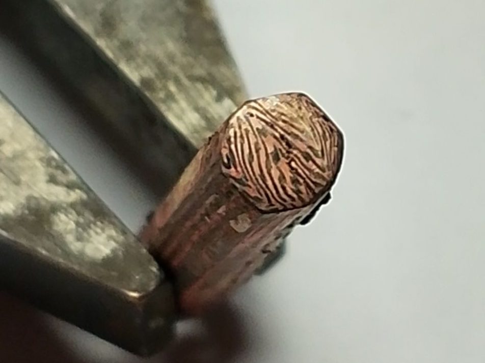
Next, I pickled to remove the flux and sanded the billet to a rough square. Before drawing the billet out, I first rolled it until the cross section was a consistent 6 x 6 mm square along the entire billet length. You can see that the top third of the pattern is the wrong way around (mirrored horizontally), as I was rushing during the stackup. The solder seams between the three layers look thick, but this is at the end of the bar where the seam gap is larger.

Next I started the process of drawing out the bar from the starting dimension of 22 x 6 x 6 mm. I annealed and pickled at 5, 4, 3.5, 3, 2.5, 2 mm thicknesses, and whenever the billet started to bend I straightened it after annealing before continuing to roll it out.
After the anneal/pickle cycle, liquid pickle was squeezed out from the billet during rolling, suggesting there were lots of cracks and voids opening up. The solder seams were horizontal to the rollers putting the joints in compression (rather than shear or tension), and I think this helped the billet to hold together despite the growing cracks.
At the final thickness of 2mm, I decided to file away the corners as they were all cracked.


This rolling process produced a compressed triple-layered “S” pattern. Next, I wanted to cut and re-stack this again to increase the layer count from 3 to 9 to create an even denser pattern.


I cut the billet into 3 lengths of 14 x 6.5 x 6 mm and sanded, fluxed and stacked these, and clamped them with steel binding wire. This time I was not worried about remelting the existing solder joints, so I soldered with medium solder (I found a spare piece). After removing the flux using pickle, I filed away the excess solder to create a rough bar, which was then rolled to a 6mm x 6mm square with sharp edges.


Next, I wanted to re-orient the patten to 45 degrees in two stages: 1) First, create an octagon using the rolling mill to deform the corners, creating four new faces, and then 2) continue to roll on these new faces to recover a square.

For stage 1, I established the corners using the 8 mm half round section of the rolling mill, rolling all four sides before decreasing the roller gap. I then moved onto the 6mm square wire section to establish the octagon shape. For stage 2 I moved to the flat section of the rollers to draw the octagon into a square.
This is where it all started to go wrong! A crack appeared at one end, along the most recently soldered seam. As I continued to roll, it opened up further and further along the bar. I attempted to repair the crack with solder by re-binding the billet in wire, fluxing, and reflowing the existing solder as well as adding some new easy solder. The joint immediately cracked open again once I rolled the billet further, suggesting the solder had not flowed into the joint.


At this point I decided to stop because: 1) the billet did not seem repairable and 2) I had achieved the aim of creating a complex cross-sectional pattern by cutting and re-stacking the billet.
To reveal the pattern from the intact end, I filed it flat, buffed to 800 grit and then oxidised with a torch. Pickling removed the copper oxide easily but did not attack the nickel oxide. This seems to be the easiest way to see the pattern quickly, and has enough contrast between the reddish-pink copper and the greenish-black nickel oxide, that it can be easily photographed.
The final pattern
Now, to see how far it’s come along, a collection of photos showing the progression of the cross-sectional pattern since the initial stackup!


I had hoped to be able to turn this billet into stock for a ring, but I think that getting the process in writing is a better use of effort than salvaging the cracked billet.
In Steve Midgett’s Mokume Gane book, Alistair McCallum mentions that “There is a tendency amongst some practitioners of mokume gane to become obsessed with the process and lose sight of the finished piece”. I relate to this heavily, as I am naturally drawn to the engineering problem solving side of making. However, in this case I am really happy that the final pattern looks fantastic. I really like the density, and I like how it looks irregular and organic enough to feel unique, but with just enough regularity/periodicity/symmetric for the pattern to appear planned and designed. Obviously, there is a long way to go but I think this is a great start.
Analysis
My short term aim is to be able to make a proof-of-concept finished piece using these patterned billets, like a ring.
The long term aim is of course process improvement, which will provide the core foundations needed to create whatever I want.
There are two questions to answer now:
- What process improvements are needed to be able to complete the bar without any cracks?
- Should I continue to pursue solder-bonded mokume, or should I invest my time into trying high-barrier-to-entry but very effective techniques such as solid-state diffusion bonding, and/or transient liquid phase diffusion bonding?
Solder-bonded nickel/copper bars – process improvement
The major process problems can be looked at chronologically.
Solder bond surface preparation:
- During this experiment I assumed that nickel oxide is dissolved by both borax flux and safety pickle. Small tests on a strip of nickel, and a quick google search, reveal that nickel oxide is very stable and is not broken down by either substance.
- I was not very diligent in making sure that the surfaces to be bonded were completely oxide-free and clean.
- This, combined with the ineffectiveness of borax flux and pickle, meant that nickel oxide was probably present in some of the solder joints which could have caused failure.
- In future, I should use sandpaper and/or files to completely remove all oxides.
- In future, I could use silver or brass instead of nickel, since these are compatible with borax flux and safety pickle.
- Or, in future, I could source a flux and pickle that do dissolve nickel oxide.
- In future, I should also flux the solder.
- Over-fluxing the layers could result in flux pockets trapped within the billet, which are not pushed out by capillary action of the solder.
- In future, I should use a thin wash of flux – enough to remove the surface oxides to allow the solder to wet the base metal, but not an excess.
Soldering
- My solder selections were all over the place!
- Given that the binding wire holds everything together, it seems safe to remelt previous joints.
- In future, I should use hard solder for all joints. On paper, hard solder has a higher tensile strength due to its higher silver content.
- I currently feed solder in from the edge and rely on capillary action to displace the flux between layers and fill the entire gap with liquid solder. It could be possible that the solder is not wicking throughout the entire seam. Steve Midgett’s book suggests only soldering one seam at a time to focus on quality not quantity.
- In future, I could try rolling out a thin solder foil and placing it between each layer. This would ensure total penetration without relying on wicking, and would extend to a large number of layers.
- Part movement during soldering was frustrating, but probably not the cause of the joints failing. It could be argued that prolonged heating duration could have vaporised the zinc in the easy solder, weakening the bond. However, this seems like a stretch, and, it was the medium solder joint that cracked and not the easy solder.
- In future, I could shape the binding wire to make the part more stable on the charcoal block during soldering.
Working the billet
- Annealing – nickel is less ductile than copper and requires more frequent annealing.
- In future, I should anneal much more often when drawing out the stock. Anneal every 0.25 mm, and then once the process works start to end without cracks, study the impact of annealing less often to save time.
- Cold shuts – when drawing out the billet, the metal gets folded over onto itself at the edges of the bar forming a “cold shut”, which is not bonded.
- In future, I should file away the outer jacket of the billet before cutting and re-stacking. This will prevent invisible cold shuts from getting embedded in the part. This wastage will need to be accounted for when the billet size is planned out.
- Steve Midgett’s book suggests that delimitation is so common that the entire side faces of billets are typically soldered before rolling them out, to make crack repair easier when it does happen.
- In future, I could accept that delamination will happen, but aim to spot it much sooner while it can still be repaired. I could inspect after every pass through the rolling mill and file away ragged edges that obscure potential cracks.
- Alternatively, for deformations that put heavy stress on the solder joint, a solid jacket could be added around the billet to provide strength during the rolling out, which would then be removed later.
- In future, if all else fails, I could solder a strong solid jacket around the billet for each cut/re-stack/rolling phase of the process, to prevent delamination.
Solder-bonded mokume vs advanced techniques
- My motivation for getting into this craft is to create finished pieces with advanced mosaic-damascus-style patterns. A creative aim is to create new novel patterns that look amazing.
- A key technical challenge is achieving strong inter-layer bonds that can withstand the extreme deformations required for this complex pattern work.
- Solder-bonded mokume is inherently limited by the relatively poor mechanical strength of solder bonds, which leads to delamination.
- Advanced techniques like solid-state diffusion bonding, or transient liquid phase (TLP) diffusion bonding are used to laminate dissimilar metals with very high bond strength. Amir Shirzadi has some great background information https://www.phase-trans.msm.cam.ac.uk/2005/Amir/bond.html. (Forge welding, as used by blacksmiths to produce mosaic patterned damascus steel, is solid-state diffusion bonding, but uses traditional equipment rather than modern lab equipment.)
- In the long term, I hope to outgrow solder-bonded mokume and learn how to do diffusion bonding.
- In the short term, I still see solder-bonded mokume as time well spent – it allows me to work towards my creative aim of producing some great proof-of-concept pieces with equipment that I already own. A lot of the skills needed are also transferable to diffusion bonding techniques.
- There are practical things to consider: solid state diffusion bonding requires an electric kiln and TLP bonding requires a gas forge or mini gas kiln. Both techniques are made easier with heavy duty steel torque plates and a hydraulic press. For space, money and safety reasons, I can’t just put these in my flat tomorrow without some planning.
- Continuing with solder-bonded mokume in the short term does delay getting started with the long term goal of learning diffusion bonding. However, it puts the primary focus on achieving the creative aim of making finished pieces now, rather than getting distracted by the technical aim of process improvement.
So, for the next post, I will re-attempt to make a complex patterned billet using soldering, and hopefully produce stock that I can transform into a finished ring!
Leave a Reply