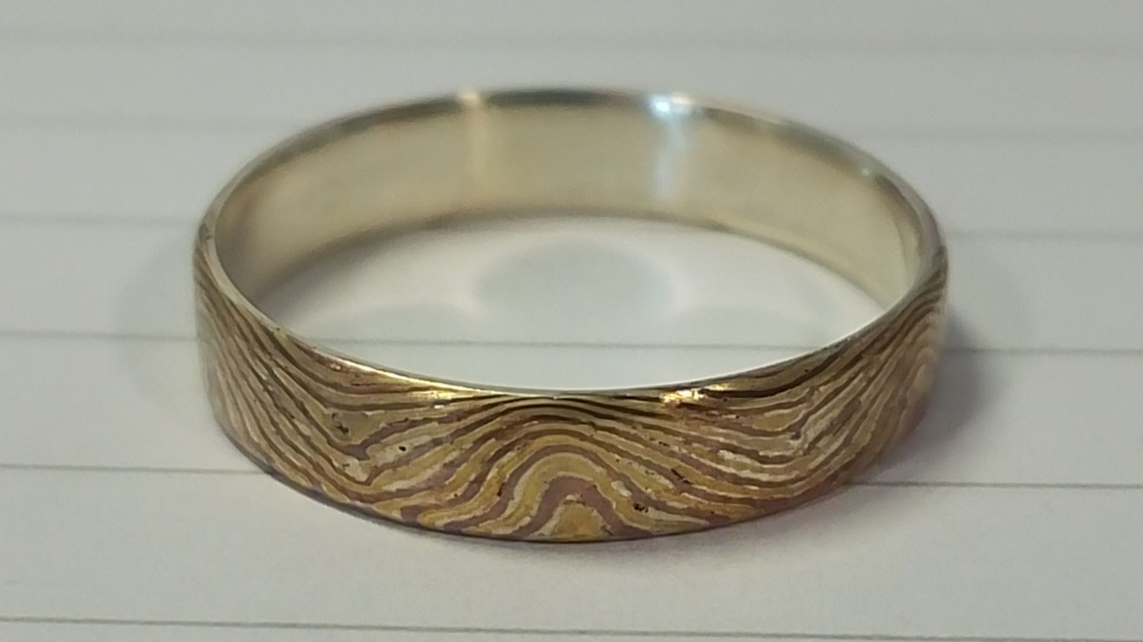
- Intro
- Method
- Material Preparation
- Soldering primary laminate
- Re-squaring the primary laminate
- Ring 1 – Accordion patterning for exposing end grain
- Ring 1 – Bonding a silver liner
- Ring 1 – Ring forming and soldering
- Ring 1 – Finishing
- Ring 2 – Rolling out the primary laminate
- Ring 2 – Secondary lamination
- Ring 2 – Accordion patterning for exposing end grain
- Ring 2 – Bonding a silver liner
- Ring 2 – Ring forming and soldering
- Ring 2 – Finishing
- Analysis
Intro
Method
Material Preparation
For this experiment I’m using copper and brass. Previously I used copper and nickel, but those laminates cracked because nickel has challenging working properties – low ductility, a high annealing temperature, and poor compatibility with borax flux and safety pickle.


I used scissors to cut 12 pieces of copper and 11 pieces of brass. Each piece was 0.3 mm thick, with a 8.3 mm width and 40 mm length.
I rolled each piece lightly using flat dies to smooth the burrs from cutting, and then annealed each piece to soften them before stacking up.
I scrubbed the oxides and oils from each piece using a scotchbrite pad and dish soap, then rinsed in water. I have a few different brands of scotchbrite and noticed that some are far more effective than others.
For this experiment I decided to trial the solder-sheet-sandwich approach for the primary lamination (rather than a wicking/direct feed method). I cut a 40 mm length of 5 mm x 0.6 mm hard silver solder wire and rolled it out to 85 um x 5.7 mm x 228 mm. Using the elongation factor of 5.7, I estimated that I would need a 119 mm piece of solder wire to roll out to 678 mm, to have enough to fill all 22 seams in the lamination. I cut this piece and rolled it out to the same 85 um thickness. To keep the wire straight I used pliers to pull the feed-in side under tension. When the wire got too long I cut it into shorter manageable sections.


I then cut x22 40 mm lengths of solder strip for the stack up, using scissors.
For the stack up, I alternated with the copper and brass sheets, interleaved with hard silver solder sheets. I used a thin wash of borax flux in between layers. Due to the similarity of brass and copper for colourblind eyes, I got confused in the stackup and ended up with a spare piece of brass by the end. In future I could cut the brass strips 1mm shorter to aid identification.
In previous experiments, the stackup was poorly aligned, meaning the layers had to be filed back to a smooth face creating lots of wastage. To address this, I used parallel pliers to align the sheets when in the vice.
Previously, the tight binding wire tended to bite into the outer strips and buckle them, creating a large gap that caused delamination. I decided to add a few sacrificial packing layers as a skin, with no solder placed in the seams for these outer strips. This did not work as expected – the binding wire still deformed the thin sacrificial strips, and created bowed layers all the way through the bar. The photo shows large gaps for every seam, made worse by this bowing, especially in the cross sectional centre of the bar. None of the strips are perfectly flat, and the binding wire does not provide enough clamping force to bring them together to close up the seams. In future, I could address this by using rigid torque plates. These are used for transient liquid phase / solid state diffusion bonding techniques, and they provide a uniform distribution of high compressive force to squash the whole bar during bonding. This would also be a step towards the more advanced techniques in future. Creating thinner seams would also mean that I could use less solder.


Soldering primary laminate
I used the small butane torch again even though I’d previously identified this as an issue. It did the job but took a long time to get the bar to soldering temperature. I may have moved the billet too early before the solder had solidified. In future I will wait for the bar to cool down before moving it. I observed that the bar sucked up a lot of molten flux, before the solder had melted. The flux was likely drawn into the large seam gaps by capillary action.
Just after soldering, there was a lot of flux around the bar.


During pickling, the flux dissolved. The solder fill looked good, but as observed during the stackup, the outer layers were bowed and deformed by the binding wire.


I filed the excess solder off, and used liver of sulphur to highlight any remaining excess solder and layer lines. This revealed the double copper layer from the stack order mixup, and the thicker copper jacket at the bar edges. The solder seam between the double layer of copper is quite thick.


Re-squaring the primary laminate
The bar started at 9.13 mm x 7.9 mm x 39.8 mm with sacrificial jackets still on. I removed the sacrificial outer jackets by heating the bar to soften the flux, and then I pried the sacrificial jacket off on one side. The other side was completely bonded, even though solder sheets were not placed between these seams. This was due to excess solder wicking out of the main bar and into these layers. On the side that did release, the wicking of the solder underneath the sacrificial outer jacket is very visible. In his book, Steve Midgett suggests to use correction fluid (TiO2) or yellow ochre paste () as a flux stop layer for releasing torque plates. This observation also suggests that less solder could be used – if the seams could be made thinner by compressing the bar, as discussed above, then less excess solder would be needed in the first place, so there would be less to wick out of the bar.


I used the rolling mill to square the bar up to 7.9 mm x 7.9 mm x 42 mm, and then filed the sharp edges off. I used the square dies (2.5 mm to 6 mm) with the bar oriented at 45 degrees, to octagonalise the cross section, annealing frequently. The bar was at the maximum width that would fit through the rolling mill square dies, and so the die edges created bite marks in the side of the bar which were filed away periodically.
I reduced the dimensions to 6.1 mm x 6.1 mm x 78.3 mm, which was required for the bar to fit into the square dies when oriented at 0 degrees.
The bar bowed and warped a lot throughout, and I straightened using the vice and parallel pliers as I went. Straightening out is important for maintaining a symmetric and regular cross section. The complex twist is due to the layered distribution of different material properties – the more complex the cross section the weirder the twist.
In future, I would file and/or polish the end cross section to improve the visibility of the layer lines in these photos.


There was no observable cracking, which was the first time this has happened. It is unknown whether this is due to changing from nickel to brass, or due to using much more solder in the seams, or both.
The octagon edges rolled over, so I filed these to avoid cold shuts later when doing secondary lamination. I re-oriented the bar to 0 degrees and used the 6 mm square rolling mill dies to complete the octagon and then re-square. This brought the bar dimensions to 5.1 m x 5.1 mm x 100 mm.
I finished the process with the flat rolling mill dies using the middle-out technique to create sharper edges. Flat dies tend to create a slight rhombus – either more practice is required or this is an inherent limitation.


At this point I filed off the outer skin to remove all of the sacrificial soldering jacket, because this may cause delamination for future secondary lamination. I used liver of sulphur as a contrast agent to highlight the copper jacket.
After rolling and filing the bar was 4.8 mm x 4.8 mm x 100 mm. I cut 4 mm off each end to remove small splits. I then cut 40 mm off as stock for ring 1, and then saved 52 mm for further pattern development.
To visualise the re-squared pattern, I filed and buffed the end of the bar and left it in Harpic toilet cleaner overnight (9% Hydrochloric acid). The pattern looks very good! The colours of the brass, copper and silver solder look really striking. The microscope pictures show there are some flux pockets and voids, but so far these have been stable and not spread as cracks. As observed during soldering, the layer seams look very thick – much thicker than the actual solder sheet thickness of 85um. The accidental double copper layer and the sacrificial copper jacket are both still visible in the bottom left corner.


It is difficult to explain why the seams are thicker than 85um. It’s possible that, due to the insufficient clamping pressure, the seams are almost 0 mm in some regions and much thicker in other regions due to the sheets bowing.
Another possibility is that the copper and brass are dissolved at the solder interface, increasing the volume of the seam.
Ring 1 – Accordion patterning for exposing end grain
Next the end grain was exposed to move the interesting cross sectional pattern to the side faces of the bar, as these will form the visible surfaces of the ring.
First I filed the outer skin to remove the copper jacket and to make the corners sharp. I used liver of sulphur to highlight the remaining sacrificial copper jacket from earlier. Next I squashed the square cross section to a rectangle using the flat dies. The dimensions changed from 4.8 mm x 4.8 mm x 40 mm to 5 mm x 4 mm x 43 mm. I widened the bar to maximise the length of each section between the bends when the accordion is unfolded. This is constrained by the height of the bar, which dictates the height of the ring.


Next I marked out the accordion pattern with 1.8 mm border lines. In future I could have allowed more material for the bend by drawing a chamfer instead of a sharp point. Next I used saws and files to cut the accordion shape out, leaving sharp internal corners and rounded external corners.


Next I began to unfold the accordion pattern. I annealed very frequently due to how aggressive the bend was, to avoid cracking the corners or delaminating the bar. I used half round pliers to squash the pattern, and after each pass I rounded the external corners using a file to reduce the material that has to compress on the outside of the bend.
Despite going slowly, there was cracking in the internal corners. In future I could have drilled a hole to relieve stress. I finished by using the rolling mill at a 45 degree entry angle to smooth out the flattened bar.


I was surprised that the accordion corners take up so much space in the pattern. This is because the 5 mm width of the bar is quite small relative to the 1.8 mm accordion thickness. In this case the unbent corners add really nice curves to the pattern, but in future I may want to minimise the accordion artefact to display only the cross sectional pattern. In this case I could roll to a more rectangular preform to provide a larger billet width, or add a sacrificial jacket to the edges. In this case I used 45 degree accordion cuts, but using a shallower angle would increase the length of the pattern between each accordion bend. There are also other methods of exposing the end grain pattern that I could explore, such as twisting the bar or using the “ferry flip” method.
Ring 1 – Bonding a silver liner
To avoid copper reacting with the skin, I decided to bond a sterling silver liner to the inside surface of the ring. I cut a 52 mm x 6.5 mm x 0.5 mm sterling silver sheet, and a matching layer of 85 um hard silver solder. I pickled both the liner and pattern before soldering. These were then stacked up with a thin wash of borax flux and binding wire was used to hold them together.


During soldering the solder sucked out of the bar and wicked around the binding wire. Also, the binding wire seemed to shift some of the pattern once the primary laminate solder melted, due to uneven clamping pressure. In future both these issues could be addressed using by clamping plates as mentioned above.
I filed the excess solder from the top and bottom faces, using liver of sulphur as a contrast agent to highlight remaining solder.
Ring 1 – Ring forming and soldering
I wanted the ring to be a size UK S, so I rolled out the stock from approximately 52 mm to 65.7 mm. Due to the complex cross section, there was lots of twist and I had to spend a lot of time straightening after every annealing/rolling step. The stock elongation smoothed out the curves, and in future I could have started with longer stock to avoid stretching the pattern.
Next I filed the ragged edges to approximately 4 mm to bring the silver liner flush with the copper and brass patterned strip. There was unfortunate pattern loss at the edges here which changed the look of the pattern. In future I could forge the copper/brass strip before bonding the silver liner so that the edges are straight and parallel. This would reduce filing wastage and pattern loss.


I bent the strip over a mandrel to form into a ring, annealing halfway. On the first soldering attempt the seam opened up during heating. I think this is due to the different coefficients of thermal expansion in the multi-metal bar, causing it to act like the bimetallic strip switches in a kettle. It could also be residual stresses that were not removed by sufficient annealing.
On the second attempt I added binding wire, and this kept the gap closed. I chose medium solder for the seam, to avoid melting the hard solder from the primary lamination. However, I struggled to get the medium solder to flow, and I ended up re-melting the hard solder anyway. The pattern stayed together, due to a combination of the surface tension of the molten solder, mechanical interlocking of the folded copper and brass layers, and the binding wire. In future I could have used easy solder to make re-melting less likely.
Next I used 280 grit sanding head in a Dremel to smooth the excess solder on the inside of the ring, then hammered the ring round on the mandrel. The size was T instead of S but luckily I also have a size T finger. This has happened previously when I have cut ring blanks to length using an online calculator. In future I could size the ring half a size smaller to account for this systematic error. Alternatively I could make my own lookup table by doing a mini study. This would give me valuable ring-soldering practice!


Ring 1 – Finishing
To finish the ring I sanded using 280/400/600/800 grit sanding head on the Dremel, rounding/chamfering the edges, and then polished with a cotton mop and Tripoli compound. I left the ring in Harpic toilet cleaner (9% hydrochloric acid) overnight to boost the pattern contrast.

Some voids remain, and it is unclear whether these arise from gas/flux voids trapped during the soldering step, or due to ripping of the solid solder when the bar was being worked. Voids are inherent limitation of the solder-bonded process. In the short term these solder-bonded pieces are still useful for practicing pattern development, but in the future I could move towards the more advanced solid-state diffusion methods.
In the microscope pictures, porosity can be seen in the solder due to de-alloying of the hard solder (the copper dissolving, leaving behind the silver). The colours look really cool! Since making the ring I have worn the ring every day and the colours change a lot depending on what my hands are doing, which makes it a really interesting piece. There is no topographic relief after etching, since brass and copper etch similarly. In future I could use silver/copper laminates which would etch differently in acid creating a surface texture. I will do this once I have refined the process to avoid expensive waste.


Overall I am really happy with the first successful finished piece, and I learned a lot!
Ring 2 – Rolling out the primary laminate
For the second ring, I decided to experiment with a more complex cross sectional pattern. I started by filing the sharp edges back in the vice, and then
rolling out the primary laminate on the corners of the pattern. The goal here was to squash the layer lines and create a wavy S pattern.


I annealed frequently and started to roll out the bar in progressively larger square dies. This established a wider flat face on the edges, which will help to keep the bar aligned in the flat dies. Next I used the flat dies to grow this flat face further and roll the cross section into a rectangle.


I rolled the bar out to a 2mm thickness.


During annealing, I had to be careful to heat the bar evenly – if the heat was focused too much on the end of the bar, the solder there melted locally and squeezed out of the seams.


Ring 2 – Secondary lamination
Cutting, re-stacking, and rolling out develops a more complex cross sectional pattern. I wanted a 6-layer secondary lamination, which I achieved in two stages. For the initial 3-layer stage, I sawed the bar into 3 equal pieces of 6.7 mm x 2 mm x 25 mm. The end cross section shows that the layer lines have been compressed into a wavy S pattern. I book matched the pieces so that the cross sections are mirror images of each other when soldered together in the next step.


I polished the faces to be soldered on a 400 grit diamond plate to flatten them. In each seam I placed a thin wash of borax flux and a 85 um sheet of hard silver solder, before wrapping the stack in binding wire. During soldering, the primary laminate solder also melted. The surface tension wicked solder around the binding wire, which appeared to pull solder out of the bar. The bar surface looked starved of solder. At first I was worried, but I think this is only superficial and the surface roughness can easily be filed away.


After soldering and filing the cross section, the pattern lines can be seen to line up very nicely, creating a wavy pattern that flows through the bar. The edge of the bar is very rough since the edges of the 3 individual pieces were rounded. In future I could roll or forge the stock more carefully before secondary lamination to improve the edge alignment. I filed away the excess solder to 6.6 mm width x 6.1 thickness x 25 mm length. I did not file all the way through the wide solder seams on the side of the bar, since there would have been a lot of wastage.
To transform this 3-layer secondary laminated bar into a 6-layer bar, I repeated the roll / cut / re-stack process.


I rolled out in the lamination direction to squash the pattern. The top and bottom edges mushroomed over, so I filed the side edges square to a rectangle, with 46.8 mm length x 7.2 mm width x 2.5 mm thickness. This also removed the ragged edge from the first stage of the secondary lamination.
For the second stage of the lamination, I cut the bar in half and repeated the process. After soldering, I filed to a neat cuboid (7 mm width and 5 mm thickness) and polished the end of the bar to visualise the pattern.


The pattern looks really cool! I like how the wavy S curves all join up together. The solder seam for the second stage is visibly thick. It is likely that too much solder was used, and the binding wire did not provide enough clamping force to squeeze it out of the joint.
Ring 2 – Accordion patterning for exposing end grain
At this point I realised that I had very little spare stock. I had a target length of 56.9 mm for the ring blank, so I needed to cut the accordion into the bar within minimum wastage. Therefore, for Ring 2 I decided to use 180 degree bends instead of the 90 degree bends used for the Ring 1 accordion.
The bar width was 7 mm and thickness was 5 mm, so I marked out a 2 mm accordion strip width using sharpie and a needle, all the way around the bar.


I split the accordion with a fret saw. Originally I planned to use a hacksaw, but the blade kerf was too wide and would have resulted in too much wastage. Instead I used 4/0 blades since I had a lot of them. These went blunt very quickly, so I used about 20 blades. If the thin kerf provided by fret saws is absolutely needed in future, I could use a coarser 1/0 blade which is intended for thicker material. When blades go blunt, they tend to wander off course, so some of the split lines were a bit wobbly.
I filed rounds onto the outside of the bends to help the material compress when unfolding. Next, I used round nosed parallel pliers to gently expand the accordion and open the bends. I did 12 cycles of annealing and pulling the bar open, taking it slow to avoid ripping the internal corners.


Despite going slowly, the inside corners still ripped due to tension. In future, I could have drilled a stress relief hole instead of just a blind stopped saw cut. The outside of the bends were filed periodically to keep the same strip thickness. However, when I got to the end, I realised I had not saved enough material on the outside of the bend, and the outside face transformed into a trough. This reduced the thickness of the flattened strip since I needed to file these troughs out.


When flattening the accordion, I did not want to use the rolling mill, since I wanted to avoid stretching and deforming the patten. Instead I used flat parallel pliers and the sides flat. one side would be the show face (needs to be fully flat), and one would be bonded to the silver liner (some scratches and troughs allowed). The inside accordion corners needed a lot of filing to get rid of the cracks caused by ripping. The outside accordion corners needed a lot of filing to get rid of the fold lines caused by removing too much material.


Filing went well, but reduced the strip thickness from 1.8mm to 0.6mm. In hindsight, I could have used the rolling mill and accepted the pattern extension. I future, I could mark out a thicker 3mm accordion strip thickness to account for filing wastage, or practice unbending accordions without cracking the material at the bends.
Some defects were left on the inner side of the strip, since this will be hidden by the silver liner. Unbending the accordion produced very interesting diamond features interleaved with the original cross section of the bar. These take up about half the space of the pattern, which is more than expected. I learned that the accordion corners will play a very strong role in the final pattern, especially when the accordion strip thickness is quite large relative to the width of the starting stock.
Ring 2 – Bonding a silver liner
As for Ring 1, I bonded a silver liner to the inside surface of the pattern. I knew that Steve Midget’s book has an alternative method, but I stuck with what I knew for this to minimise risk. In future I could attempt other methods. I cut a sterling silver backing strip (0.5 mm x 5.5 mm x 50 mm) with scissors from a scrap plate, and rolled it to increase the length, producing a 59 mm x 0.4 mm x 5.9 mm strip. I cut a piece of 12 mm x 0.6 mm x 5 mm hard silver solder, rolled it out to 78 mm x 85 um x 5.8 mm, then cut the width to 4.2 mm, to reduce excess solder in the joint.
For Ring 1, soldering the pattern to the silver backing strip disrupted the pattern, due to the uneven binding wire clamping force causing sliding of brass/copper layers around once the lamination solder joints had re-melted. Also, the binding wire sucked up the solder due to surface tension, required a lot of cleanup. To address this, I placed a copper jacket above the pattern, underneath the binding wire. The idea was that it would spread out the clamping force, and stop the wicking around into the twisted wire. To stop the solder wetting the copper jacket, I painted correction fluid (Titanium Dioxide) on the copper surface. I applied 2 layers, drying them on a warm charcoal block.


During soldering, the copper jacket made it difficult to see the solder flow, but it did flow all the way around. The copper jacket released very easily due to the Titanium Dioxide barrier. The pattern solder seams re-melted and some voids opened up, especially where the pattern seams are thicker along the centreline. The pattern centreline turned into a slight trough, so I filed the strip to recover a flat surface. I also filed the width flush to produce a clean edge.


The pattern had excess length (82mm) for the ring size I wanted, so I cut the ends off producing a final ring blank of 1 mm thickness x 59mm x 5 mm width.
I buffed the file marks from the outer face of the bar while it was flat, since I find this easier than buffing after the ring is bent.


Ring 2 – Ring forming and soldering
I bent the ring around a mandrel in two stages, annealing in between. I noticed the pattern pull apart from itself when the outer surface was under tension. Small ripples could be seen on the surface which could be the layers shifting, or the solder bonds stretching. In future I could use the Steve Midget method where the pattern strip and silver liner are made into rings separately and then nested inside each other and soldered – this would reduce the tension on the pattern strip during bending.


Next, I sawed through the ring seam to produce flushed ends, and bound the ring together using binding wire to prevent it from opening up when heated. I used easy solder to avoid re-melting the hard silver solder used for lamination. The easy solder didn’t flow very well, but the seam filled. I cleaned up the solder on the inside of the ring with a 220 grit Dremel abrasive wheel, then hammered the ring to a round on the mandrel.
Ring 2 – Finishing
I finished the ring using Dremel abrasive wheels from 220 grit to 1000 grit, and then polished with Tripoli and a cotton mop. I ran out of buffing sticks, so had to use the Dremel wheel on the outside of the ring too. This makes it tricky to get a smooth fare curve, as the wheel tends to dig into indents.
The microscope photos below were taken after leaving the ring in Harpic toilet cleaner (9% Hydrochloric acid) overnight, to bring out the colours of the copper, brass and solder.


There are lots of voids in the solder – at first I attempted to sand them out, but once I realised that they permeated the material, I made peace with them. The solder voids could be flux inclusions or porosity from the multiple soldering steps, or they could be cracks from working the bar. Regardless, voids are a well known limitation of solder bonded mokume, and in the future I could experiment with the more advanced solid state diffusion or transient liquid phase diffusion bonding techniques. Also, as discussed above, in future I could apply a large uniform clamping force during the lamination steps to reduce the thickness of the solder seams. Even if this does not eliminate voids, it would reduce their visibility in the final piece.
Overall, I am really happy with the complexity of the pattern, and the colours under the microscope are beautiful. The dense pattern is quite hard to appreciate from a distance. Mokume Gane takes it’s name from wood grain, and something that I like about wood grain is that it has macro patterns that you can see from a distance and micro patterns that you can only see up close. In future, I could try to incorporate a mixture of macro and micro patterning so that the piece has something to offer from a distance and up close. The honest reason for incorporating dense complex patterning, is that it shows technical skill and that it sets a piece apart from what has been done commonly before. It was driven as much by the ego of the maker as what the piece “needed”.
The dense pattern may have looked bolder if the execution had been better. The voids, and thick central pattern seam in the final piece detract from the flow of the pattern. Clamping the solder seams during lamination may improve the look of the pattern in future.
The pattern may have looked better if the layers were thicker. In the microscope pictures the brass layers are incredibly thin and are only visible up close. This may be due to the brass dissolving into the hard silver solder. In future, I could experiment with using thicker sheets in the primary lamination, or using sheets of a different thickness, or adding new sheets at the secondary lamination stage.
The pattern is also very regular, and lacks organic curves and unpredictability. In future, I could add more elements, thinking outside the box to make the piece unique.
Analysis
Below is a summarised list of points of improvement for the future.
Material Preparation
- Cut brass strips 1 mm shorter to aid identification during stack-up
- Use rigid torque plates to provide uniform high compressive force during bonding, reducing seam gap and solder usage
- Use less solder — if seam gaps are reduced by clamping, less excess solder wicks out in the first place
Soldering primary laminate
- Wait for the bar to cool before moving it after soldering
Re-squaring the primary laminate
- Use correction fluid (TiO₂) or yellow ochre paste as a flux stop on sacrificial/torque plates
- File and/or polish the end cross section at each stage to improve visibility of layer lines in photos
Ring 1 – Accordion patterning
- Draw a chamfer rather than a sharp point when marking out the accordion, to allow more material at the bend
- Drill a stress relief hole at internal corners rather than a blind stopped cut, to avoid cracking
- Roll to a more rectangular preform or add a sacrificial jacket to edges to minimise the accordion artefact
- Use a shallower accordion cut angle to increase pattern length between bends
- Explore alternative end-grain exposure methods: twisting, or the “ferry flip”
Ring 1 – Bonding a silver liner
- Use clamping plates instead of binding wire to prevent layer shift and solder wicking during soldering of the silver liner
Ring 1 – Ring forming and soldering
- Forge the copper/brass strip before bonding the silver liner so edges are straight and parallel, reducing filing wastage and pattern loss
- Start with longer stock to avoid stretching the pattern during elongation to ring size
- Size ring blanks half a size smaller to account for systematic size error, or create a personal lookup table by doing a mini study
Ring 1 – Finishing
- Try silver/copper laminates which etch differently in acid, creating topographic surface relief
- Move towards solid-state diffusion bonding to eliminate voids inherent to the solder-bonded process
Ring 2 – Rolling out the primary laminate
- Heat bar evenly during annealing to avoid locally melting solder at the ends
Ring 2 – Secondary lamination
- Roll or forge stock more carefully before secondary lamination to improve edge alignment
Ring 2 – Accordion patterning
- Use coarser 1/0 fret saw blades rather than 4/0 when thin kerf is needed in thicker material
- Drill stress relief holes at internal corners instead of blind stopped saw cuts
- Mark out a thicker accordion strip (e.g. 3 mm) to account for filing wastage
- Accept or deliberately incorporate accordion artefacts as a dominant pattern element
- Use the rolling mill and accept pattern extension rather than filing, to preserve strip thickness
Ring 2 – Bonding a silver liner
- Use Steve Midgett’s method of forming pattern strip and silver liner into rings separately, then nesting and soldering, to reduce tension on the pattern strip during bending and risk of layer shift
Ring 2 – Finishing / General
- Apply large uniform clamping force during lamination to reduce solder seam thickness and void visibility
- Experiment with thicker sheets in primary lamination, varying sheet thickness, or adding fresh sheets at secondary lamination stage, to keep brass layers visible
- Incorporate a mix of macro and micro patterning so the piece reads at distance as well as up close
- Add more unpredictable or organic elements to avoid regularity in the pattern
Leave a Reply