Summary Pictures
Spoiler alert: cracks!


Intro
The aim of this experiment is to make a ring from nickel/copper mosaic patterned bar. This will be a proof of concept, before moving onto more expensive metals in the future.
In previous experiments (Continuing the Nickel/Copper patterned billet) I achieved complex cross sectional patterns in a nickel/copper billet, but the billet delaminated during rolling.
First I plan to repeat the manufacture of a mosaic patterned nickel/copper billet, implementing some process improvements that came out of analysing the previous failures.
Then, I plan to get creative and transform the billet into a ring.
Method
Material selection points to address from last time:
- I’m using nickel again even though nickel oxide is not broken down easily by borax flux and safety pickle. To address the nickel oxide temporarily, I am using mechanical scrubbing. In parallel I have ordered brass sheet to use as an alternative contrast metal for future experiments.
- I have found a very small amount of hard and medium solder to hopefully create stronger bonds. In parallel I have ordered some bulk hard solder, but over the holiday period it has not arrived, and I am impatient to start! I accept that the billet may delaminate at some point.
I wanted to increase the size of the initial stackup to account for cracked parts of the billet that have to be cut or filed off at each step. The stackup was x23 layers of 0.3 mm sheet, each with a 8 mm width and 40 mm length. This gives a theoretical stacked height of 8.05 mm assuming a solder thickness of 50 um. This gives 12 layers of copper and 11 layers of nickel.
I cut the pieces with scissors, which makes them curl heavily. I ran them through the rolling mill set to 0.35 mm to remove the major twist, at both 0-degree and 45-degree entry angle.
Then, I annealed the pieces. It helps if they are dead soft during the stackup so that the layers can be flattened, and for the binding wire to close up the small gaps between layers. After annealing I rolled the strip at 0.325 mm to remove any residual twist.
Next, I removed the copper and nickel oxides to expose bare metal, using soapy water and a scouring pad. Each piece was rinsed twice in tap water and handled only using tweezers and a paper towel to dry it. The nickel oxide was very hard, and extremely time consuming to scrub away.


Since I had a very small supply of solder, I decided to split it into 22 parts to ration it between the layers. I was not confident that feeding the solder into the stack while hot would feed all of the seams evenly. This was also an idea from the previous experiment, although I had imagined interleaving the nickel and copper with a full sheet of solder between every layer gap, and not rationing so heavily.
I rolled out the hard solder to 6 mm x 105 mm, at the absolute minimum thickness on my rolling mill (which is not 0 mm due to play in the mechanism). It was 85um thick. To roll the solder this thin I had to anneal it, and I nearly melted it. I then cut the hard solder into 1 mm x 35 mm strips. This caused curling, so I put each strip back through rolling mill to flatten it, which caused the length to increase to 42 mm, making the solder even thinner. This suggests the absolute minimum rolling mill thickness depends on the width of the item being rolled which is interesting! Finally, each strip was cut in half to produce two 1 mm x 21 mm solder strips per layer gap in the stackup.


Next I carefully stacked up the billet. A thin wash of borax flux was applied to all surfaces, including the solder. Interestingly the flux wet the surface of the copper and solder very easily, but not the nickel surface, even though the oxides had been scrubbed away. This may need to be revisited if nickel is used for future experiments.
Primary Lamination
The stackup was clamped with parallel pliers and placed in the vice, and then wrapped in stainless steel binding wire. Slight layer shifting occurred.


During soldering most of the seams did not weep solder. To remedy this, I fluxed some scraps of medium solder and directly fed them into the seams. However, the total solder fill was still poor due to the limited quantity of extra solder. I held the bar at soldering heat for a very long time, and this seemed to burn off all of the flux.


I filed all the ragged faces flat, and removed the loose outer copper jackets which were buckled due to the wire wrap. This created a large inter-layer gap that was not filled with solder. Many of the seams were visibly unfilled in some regions, but the solder penetration was much better than expected, given the very small quantity of solder used.


To square the bar, I rolled out using the flat dies from 7.5 mm x 6.3 mm x 39 mm to 6 mm x 6 mm x 49 mm. I annealed every 0.25mm, and filed rough edges when they emerged. I annealed hot because I read somewhere that nickel needs this – I stopped when tiny balls of solder weeped out of seams.
During rolling, lots of borax flux squeezed out of the seams, indicating poor solder flow and lots of flux pockets.


Interestingly, there is a visible difference between behaviour of copper and nickel under the rolling dies – the copper seems to stretch further, seen in the jagged edge at the end of the bar.


Re-squaring the primary laminate
Once the bar had a square cross section, I started to re-square it. The goal of re-squaring is to deform the layers into wavy “S” and “C” patterns.

I started the octagonalisation process by rolling corners on the 8mm half round dies.


Next, I turned the bar 45 degrees and moved to the 4 mm square dies to create larger chamfers on the edges. I discovered a crack at one end due to lamination failure.


Next, I moved up to the 5 mm square dies to make the edge chamfer larger. The end crack was much worse with visible layer shifting, so I cut it off. Here the development of the wavy pattern can be seen.


I moved up to 6 mm square dies to finish establishing the octagonal faces with large chamfers.


I moved to the flat dies to make these chamfers even larger, in order to fully develop the octagon. However, feeding accurately into the flat dies was challenging and the bar started to twist. I fed the bar in from both ends, and the octagon facets did not meet up in the middle.


To recover the octagonal faces, I hand forged the corners to even out the facets. Marking out bad facets with permanent marker helped alignment during forging.


I moved back to flat dies again, to smooth out the hammer marks. I started experimenting with a middle-entry technique on the rolling mill: 1) adjust the roller gap to be thicker than the bar, 2) hold the bar between the roller dies 3) reduce the roller gap until the roller dies clamp and deform the bar 4) roll back and forth to squeeze the part. This was fiddly at first, but reduced the twisting a lot, since the part self-orients under the roller pressure
Throughout this process, the crack at the end started to split again, and the other end started to split also.


The cross section was now a regular octagon. To finish the re-squaring process, I moved back to the 6 mm square dies, but with the primary layer lines now oriented perpendicular to the rolling mill. I rolled the cross section past octagon into square again leaving small edge chamfers.


Rolling out the primary laminate
I wanted to create complex wavy “S” and “C” patterns, which can be done by squashing a re-squared billet in the direction of the layer lines.
First, I cut the cracks off end. Then, I rolled the bar using flat dies to squash the pattern. Slippage caused the octagon to rotate. A flux pocket can be seen in the middle of the bar.


I used a hammer to manually adjust the cross section. Major delimitation emerged, which was probably caused by poor solder flow and/or flux pockets during the primary lamination.


I continued rolling out using flat dies, cycling between rolling / straightening / annealing to reduce the bar to 2.2 mm thickness. The edges became very ragged due to the nickel cracking.


I used a mix of sawing and filing to remove the ragged edges from all 6 faces of the bar, and cut the heavily cracked ends of the bar off. Filing proved much more successful than sawing – the blade got blunt and wandered.


The primary pattern development was complete, and the goal of creating wavy “S” and “C” patterns was achieved.


Secondary lamination
Rolling out the primary laminate was essential for pattern development, but it reduced the bar thickness. The goal for secondary lamination was to recover a square cross section for further processing.
I lapped the faces to be solder-bonded on a 400 grit diamond plate. This was done to keep the solder seam thin and remove deep scratches with oxides/dirt that could contaminate the solder bond. Lapping exposed some voids that likely go through the entire bar. These are probably caused by solder bonds failing. The nickel layers were visibly cracked/fragmented, while the copper layers remained intact, due to the higher ductility of copper.


The 3 pieces were clamped in binding wire and soldered together with a rolled 80um thickness hard solder sheet interleaved between each seam.This was an idea from a previous experiment, made possible with the arrival of some new hard solder. This avoids the need for direct feeding the solder into the joint.
After soldering I filed the ragged edges and buffed the cross section on each end to inspect the bond lines and pattern. Surprisingly, the solder lines look much thicker than the 80um solder sheet.


Re-squaring the secondary laminate
The technique of repeated lamination/re-squaring/rolling out is used to create patterns with a mixture of small and large features, similar to a fractal. I wanted to experiment with this effect, so I repeated the re-squaring process of the secondary laminated billet.


Cracks developed very often, and had to be cut off. (drawn picture of pattern development)
I used flat rolling dies and parallel pliers to square and straighten the bar after secondary lamination, producing a 5.1 mm x 5.1 mm x 28 mm billet. Next, 2.5 mm square dies were used to start octagonalisation by chamfering the corners (bar oriented at 45 degrees). This was repeated with 4mm, 5mm, and 6mm square dies. Once the octagon diagonal faces were fully established, I rotated the bar back to 0 degrees so that the secondary layer lines were parallel to the flat dies. I continued until resquaring was complete with a 4.6 x 4.6 x 38 mm square billet.
Rolling out the secondary laminate
Rolling out the resquared laminate is used to distort the secondary layer lines to create a more complex pattern. I used flat rolling dies with the middle-out technique, flattening the bar to 2 mm thickness, annealing every 0.3 mm.
After the primary stage, I liked the way the layers had folded organically, but the secondary stage seemed to undo all of this by stretched the layers out again, making the pattern less curly. Next time I could have repeated the re-stacking process at least twice during the secondary lamination, to create a higher secondary layer count of at least 9 instead of just 3.


Tertiary lamination
I decided to do another round of lamination/re-squareing to achieve a pattern I was happy with.
I cut the billet in half, lapped the surfaces and restacked using a hard solder sheet again to create a tertiary layer structure. This produced a 4.5 x 4.5 x 25mm billet. This returned the pattern to a square shape and restored some of the pattern complexity.


Re-squaring the tertiary laminate
Next, I wanted to re-square again to add some curvature back into the pattern, since the overall feel was still very linear despite the small curls and waves.

I filed the excess solder, and squared on flat rolling dies to produce a 4.3 x 4.3 x 25mm billet. I used 2.5mm, 4mm, and then 5mm square dies at 45 degrees to begin octagonalisation by chamfering the corners. I then rotated back to 0 degrees, and used 5 mm square dies to create a regular octagonal cross section. I moved to flat rolling dies with the middle-out technique on the new faces, to return the cross section to a square.
Flux weeped out of the tertiary soldered seams during rolling, indicating that there are flux voids trapped inside the solder. This is known to be a problem for solder-bonded mokume game bars.
Throughout the re-squaring, cracks kept developing at the ends, and I cut off 3-5 mm at a time whenever this happened. Eventually, the cracks were propagating very far from both ends and nearly meeting in the middle of the bar, so I decided this bar was done, and stopped the experiment.
Cross-section contrast enhancement
I cut, filed, sanded, and polished the ends of the bar for pattern visualisation. Shiny metal is difficult to photograph.


To achieve contrast between the nickel and copper, I oxidised the ends of the bar with a flame, and then removed the copper oxide in pickle revealing orangey-pink copper, leaving the dark nickel oxide intact. This process is unreliable and I can’t get very consistent results. It seems to produce a stronger contrast when done in cold pickle. Flux trapped within the bar usually re-melts and weeps out the end of the bar obscuring the pattern.
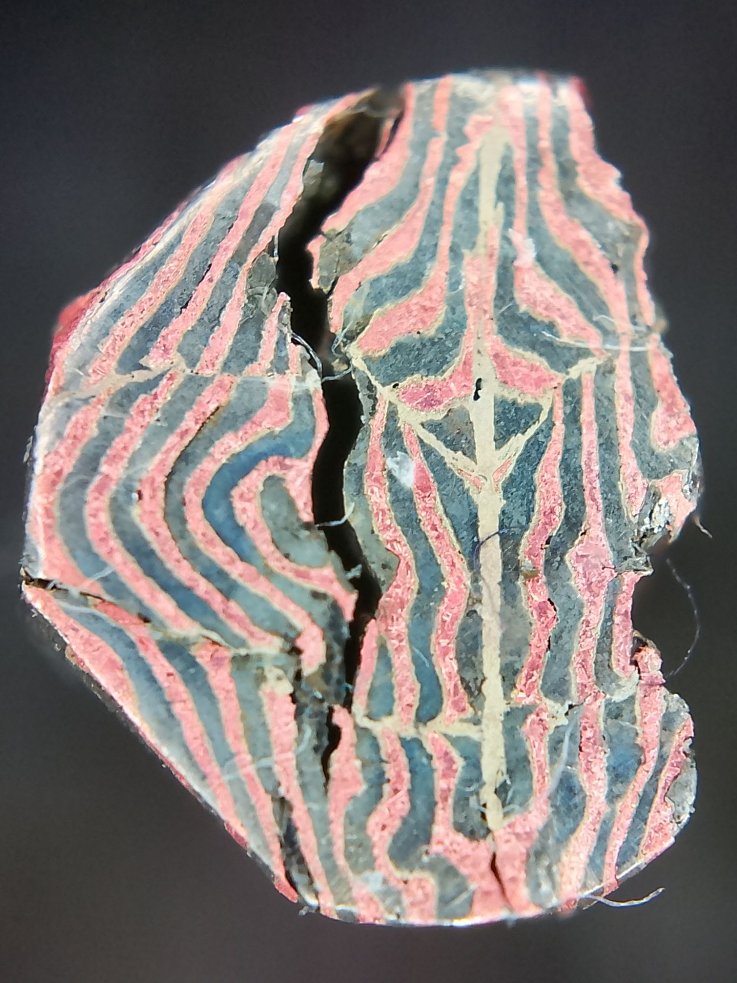
I used a clip-on microscope lens for my phone camera to get these pictures of the final cross section of the billet. Two cracks can be seen on both ends, which have filled with abrasive particles and sanding debris from my buffing sticks.


I peeled the outer part to fully separate the crack. Inside, there is so much oxidation that it is difficult to tell whether the solder, copper, or nickel failed. From the end cross-section, it looks like the seams in the primary lamination step failed, rather than the re-stacking.


I also tried immersing the pieces in Harpic toilet cleaner (9% Hydrochloric acid) overnight. This produced a much clearer contrast between the copper/solder and nickel. The toilet cleaner removed the flux residue and dissolved the material in the cracks. This technique produced great visual results but was very slow.
With this contrast, it can be seen that the cracks are approximately symmetric about the tertiary solder seam. This is consistent with the theory that the defect was pre-existing in the primary lamination.
Analysis
It is a shame that the billet failed before the aim of transforming the stock into a ring could be achieved. However, 1) I originally started this experiment fully aware that it might delaminate, because I was too impatient to wait for hard solder to arrive in the post. 2) I learned a huge amount of other things e.g. rolling out and pattern development, so it was not a waste of time. The learnings can be grouped into the following categories:
Material selection:
- On the previous experiment I questioned whether nickel is an overly ambitious material choice for someone learning this technique for the first time. I ordered brass sheet, but started this experiment before it arrived.
- I read that nickel requires hot annealing temperature, and so I heated the bar until it glows very brightly (well beyond a dull red). Often, small balls of solder weeped out of the seams, at which point I stopped, waited until the glow disappeared, and then quenched in pickle.
- Upon further research, nickel anneals at 705–925°C which is very high compared to 370–650°C for copper and 425–590°C for brass. Hard silver solder typically has a melting point around 745–780°C.
- I don’t know the detailed metallurgy, but I have read that reflowing the solder many times (and/or holding the solder above melting temperature for extended periods) can cause the solder joint to degrade.
- Nickel also has a much lower ductility than copper and brass, making it prone to cracking during rolling out.
- These factors, along with the incompatibility with safety pickle and borax, suggest that nickel is an unsuitable material choice for learning this technique.
- In future, I should use copper/brass laminates instead of copper/nickel.
Solder technique:
- The solder sheet method produces thick seams, but was not observed to fail. If the thick seams are a problem later, this could be investigated separately. I’ve never used the solder sheet sandwich method for primary lamination, so this needs testing.
- In future, I should continue to use the solder-sheet-sandwich method.
- When the billet is large (near the beginning of the process before wastage/cut-offs), heating times were very long due to the large thermal mass. This was inconvenient, and increased the time the solder was molten for.
- In future, I should use a more powerful torch to minimise time at heat.
Rolling:
- I learned the square dies are more suited to chamfering than the round dies.
- I learned that the square dies can be used at both 0 degrees and 45 degrees at different stages in the re-squaring process.
- I learned that flat dies often lead to unintended twist/rocking and should be used only when the bar no longer fits in the square dies.
- I learned the middle-out-technique.
- I learned that straightening the bar is essential (including removing twist), especially before using the flat dies.
Pattern development / design:
- I am noticing a trend that ambitious complex patterns require more working and therefore are more likely to crack before the stock can be transformed into a finished piece e.g. a ring. A proof of principle finished piece is the current main aim.
- I should limit the next experiment to a primary lamination/re-square only, and then build it back up from there once successful.
Delamination:
- The crack can be traced back to void in the primary lamination, probably due to incomplete solder flow and flux pockets. This was opened up during the primary re-squareing, and became the weak point during the later steps.
- In the previous experiment analysis, I had the idea of adding a solid jacket around the billet to help resist delamination.
- I think this is still a good idea, but I only want to do this if I absolutely need to, i.e. if I find that solder alone is fundamentally insufficient as a bonding method for these kind of patterns.
Wastage:
- The bar shrunk a lot from its original dimensions, due to cutting off the ends to stop cracks propagating.
- Given I am only doing a primary lamination / re-square, I will stick with the same starting stock size.
- In future, if doing a secondary/tertiary patterned bar, I would need to increase the size of the starting stock to account for wastage.
Patina:
- For quick contrast visualisation, I found filing, oxidising, and quenching in cold pickle produced the strongest contrast between copper and nickel.
- Hydrochloric acid produced excellent contrast, but took hours.
- In future, I could experiment with warm/hot hydrochloric acid for producing fast contrast between copper and nickel.
Leave a Reply